Thinking about risk through methods

Risk management is  a topic with a large number of methods. Within the process industries, semi-quantitative methods are popular, in particular for determining required SIL for safety instrumented functions (automatic shutdowns, etc.). Two common approaches are known as LOPA, which is short for “layers of protection analysis” and Riskgraph. These methods are sometimes treated as “holy” by practicioners, but truth is that they are merely coginitive aids in sorting through our thinking about risks.


13768080_1067660556651700_1098663203_n
Riskgraph #sliderule – methods are formalisms. See picture on Instagram


In short, our risk assessment process consists of a series of steps here:

  • Identify risk scenarios
  • Find out what can reduce the risk that you have in place, like design features and procedures
  • Determine what the potential consequences of the scenario at hand is, e.g. worker fatalities or a major environmental disaster
  • Make an estimate of how likely or credible you think it is that the risk scenario should occur
  • Consider how much you trust the existing barriers to do the job
  • Determine how trustworthy your new barrier must be for the situation to be acceptable

Several of these bullet points can be very difficult tasks alone, and putting together a risk picture that allows you to make sane decisions is hard work. That’s why we lean on methods, to help us make sense of the mess that discussions about risk typically lead to.

Consequences can be hard to gauge, and one bad situation may lead to a set of different outcomes. Think about the risk of “falling asleep while driving a car”. Both of these are valid consequences that may occur:

  • You drive off the road and crash in the ditch – moderate to serious injuries
  • You steer the car into the wrong lane and crash head-on with a truck – instant death

Should you think about both, or pick one of them, or another consequence not on this list? In many “barrier design” cases the designer chooses to design for the worst-case credible consequence. It may be difficult to judge what is really credible, and what is truly the worst-case. And is this approach sound if the worst-case is credible but still quite unlikeley, while at the same time you have relatively likely scenarios with less serious outcomes? If you use a method like LOPA or RiskGraph, you may very well have a statement in your method description to always use the worst-case consequence. A bit of judgment and common sense is still a good idea.

Another difficult topic is probability, or credibility. How likely is it that an initiating event should occur, and what is the initating event in the first place? If you are the driver of the car, is “falling asleep behind the wheel” the initating event? Let’s say it is. You can definitely find statistics on how often people fall asleep behind the wheel. The key question is, is this applicable to the situation at hand? Are data from other countries applicable? Maybe not, if they have different road standards, different requirements for getting a driver’s license, etc. Personal or local factors can also influence the probability. In the case of the driver falling asleep, the probabilities would be influenced by his or her health, stress levels, maintenance of the car, etc. Bottom line is, also the estimate of probability will be a judgment call in most cases. If you are lucky enough to have statistical data to lean on, make sure you validate that the data are representative for your situation.Good method descriptions should also give guidance on how to do these judgment calls.

Most risks you identify already have some risk reducing barrier elements. These can be things like alarms and operating procedures, and other means to reduce the likelihood or consequence of escalation of the scenario. Determining how much you are willing to rely on these other barriers is key to setting a requirement on your safety function of interest – typically a SIL rating. Standards limit how much you can trust certain types of safeguards, but also here there will be some judgment involved. Key questions are:

  • Are multiple safeguards really independent, such that the same type of failure cannot know out multiple defenses at once?
  • How much trust can you put in each safeguard?
  • Are there situations where the safeguards are less trustworthy, e.g. if there are only summer interns available to handle a serious situation that requires experience and leadership?

Risk assessmen methods are helpful but don’t forget that you make a lot of assumptions when you use them. Don’t forget to question your assumptions even if you use a recognized method, especially not if somebody’s life will depend on your decision.

SIL and ballast systems

Working on floating oil and gas facilities, one question keeps popping up about ballast systems. Should they have SIL requirements, and what should in this case the requirements be? When seeking to establish requirements for such systems, several issues are uncovered. First of all, current designs of ballast systems are very robust due to evolution of designs and requirements in shipping over a long time. Further, the problem is much more complex than collecting a few well-defined failure modes with random error data leading to a given situation, as typically seen in may process industry type problem descriptions. This complexity depends on a number of factors, and some of them are specific to each ship or installation, such as location, ship traffic density or operating practices of personnel onboard. Therefore, any quantitative estimates of “error probabilities” contributing to an expected return frequency of critical events concerning the system will have significant uncertainties associated with them.

ship-storm1

A ballast system is used to maintain the stability of a ship or a floating hull structure under varying cargo loading conditions and in various sea conditions and ship drafts. Water is kept in tanks dispersed around the hull structure, and can be pumped in or out, or transfered between tanks, to maintain stability. Errors in ballasting operations can lead to loss of stability, which in the worst consequence means a sunken ship. The ballasting operation is normally a semi manual operation where a marine operator would use a loading computer to guide decisions about ballasting, and manually give commands to a computer based control system on where to transfer water into or out of a particular ballast tank. Because this is such a critical safety system it is a natural question to ask: “what are the performance requirements?”.

Ballast systems have been part of shipping for hundreds of years. Requirements for ballast systems are thus set in the classification rules of ship classification societies, such as Lloyd’s Register, DNV GL or ABS. These requirements are typically presecriptive in nature and focus on robustness and avoidance of common cause failures in the technology. Maritime classification societies do not refer to safety integrity levels but rely on other means of ensuring safey operation and reliability. Society has accepted this practice for years, for very diverse vessels ranging from oil tankers to passenger cruise ships.

In oil and gas operations, the use of safety integrity levels to establish performance requirements for instrumented safety functions is the norm, and standards such as IEC 61508 are used as the point of reference. The Norwegian Oil and Gas Association has made a guideline that is normally applied for installations in Norwegian waters, which offers a simplification of requirements setting based on “typical performance”. This guideline can be freely downloaded from this web page. This guideline states that for “start of ballasting for rig re-establishment”, ths system should conform to a SIL 1 requirement. The “system” is described as consisting of a ballast control node, 2 x 100% pumps and three ballast valves. In appendix A.12 of the guideline a description of this “sub-function” is given with a calculation of achievable performance.

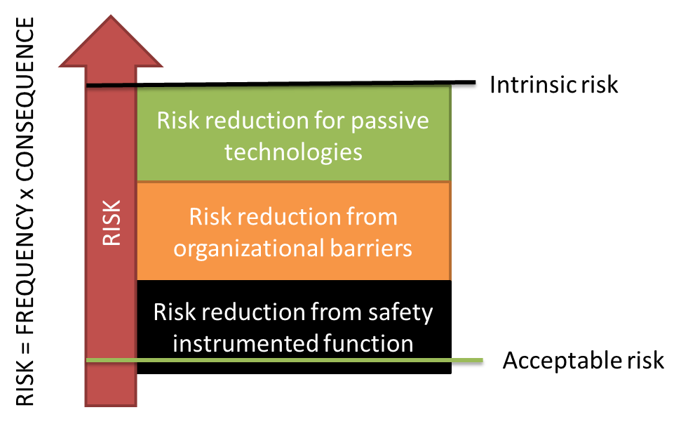
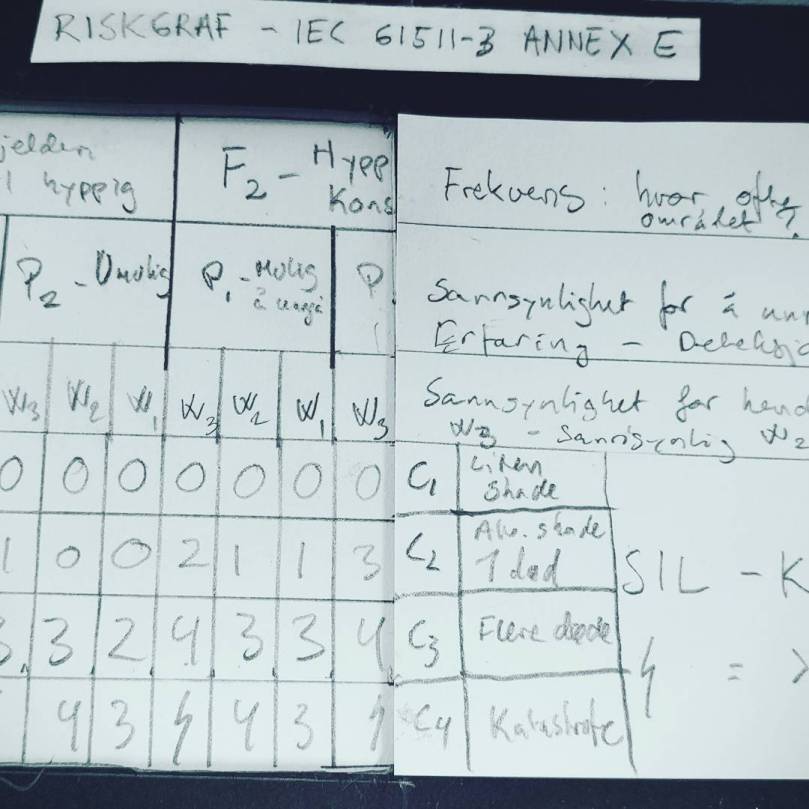
It may be argued that this functional description is somewhat artificial because the ballast system on a production installation is normally operated more or less continously. The function is defined for a single ballast tank/compartment, irrespective of the number of tanks and the necessary load balancing for re-establishing stability. The Guideline 070 approach is based on “typical performance” of the safety system as it is defined, and is not linked directly to the required risk reduction provided from the system. Multiple approaches may be taken to assign safety integrity levels based on risk analysis, see for example IEC 61508. One such method that is particularly common in the process industries and the oil and gas industry is “layers or protection analysis”, or LOPA for short. In this type of study, multiple initating events can contribute to one hazard situation, for example “sunken ship due to loss of stability”. Multiple barriers or “independent protection layers” can be credited for reducing the risk of this hazard being realized. In order to use a risk based method for setting the integrity requirement, it is necessary to define what is an acceptable frequency of this event occurring. Let us say for the sake of the discussion that it is acceptable that the mean time between each “sunken ship due to loss of stability” is 1 million years. How can we reason about this to establish requirements for the ballast system? The functional requirement is that we should “be able to shift ballast loading to re-establish stability before condition is made unrecoverable”. In order to start analyzing this situation, we need to estimate how often we will have a condition that can lead to such an unrecoverable situation if not correctly managed. Let us consider three such “initiating events”:

  • Loading operator error during routine ballasting (human error)
  • Damage to hull due to external impact
  • Error in load computer calculations

Both of these situations depend on a number of factors. The probability that the loading operator will perform an erronous situation depends on stress levels, competence/training and management factors. A throrough analysis using “human reliability analysis” can be performed, or a more simplified approach may be taken. We may, for example, make the assumption that the average operator makes 1 error without noticing immediately every 100 years (this is an assumption – must be validated if used).

Damage to hull due to external impact would depend on the ship traffic density in the area, if there is a difficult political condition (war, etc.), or if you are operating in arctic environments where ice impact is likely (think Titanic). Again, you may do extensive analysis to establish such data, or make some assumptions based on expert judgment. For example, we may assume a penetrating ship collition every 100 years on average.

What about erros in load computer calculations? Do the operators trust the load computer blindly, or do they perform sanity checks? How was the load computer programmed? Is the software mature? Is the loading condition unusual? Many questions may be asked here as well. For the sake of this example, let us assume there is no contribution from the loading computer.

We are then looking at an average initiating event frequency of 0.1 for human errors and 0.01 for hull damage.

Then we should think about what our options for avoiding the accidental scenario are, given that one of the initiating events have already occurred. As “rig re-establishment” depends on the operator performing some action on the ballast system, key to such barriers is making the operator aware of the situation. One natural way to do this would be to install an alarm for indicating a dangerous ballast condition, and train the operator to respond. What is the reliability of this as a protection layer? The ballast function itself is what we are trying to set the integrity requirement for, and any response of the operator requires this system to work. Simply notifying the operator is thus necessary but not enough for us. In case the ballast system fails when the operator tries to rectify the situation, the big question is, does the operator have a second option? Such options may be a redundant ballast system, not using the same components to avoid common cause failure. In most situations the dynamics will be slow enough to permit manual operation of pumps and valves from local control panels. This is a redundant option if the operator is trained for it. If the alarm does not use the same components as the function itself, we have an independent protection layer. The reliability of this, put together with the required response of a well-trained operator cannot be credited as better than a 90% success rate in a critical situation (ref. IEC 61511, for example).

So, based on this super-simplified analysis, are we achiving our required MTTF of 1 million years?

Events per year: 0.02.

Failure in IPL: Alarm + operator response using local control panels: 0.1.

OK, se we are achieving an MTTF of:

1/(0.02 x 0.1) = 500 years.

This is pretty far from where we said we should be. First of all, this would require our ballast system to operate with better than SIL 4 performance (which is completely unrealistic), and furthermore, it includes the same operator again performing manual actions. Of course, considering how many ships are floating at sea and how few of them are sinking, this is probably a quite unrealistic picture of the real risk. Using super-simple tools for adressing complex accidental scenarios is probably not the best solution. For example, the hull penetration scenario itself has lots of complexity – penetrating a single compartment will not threaten global stability. Furthermore, the personnel will have time to analyze and act on the situation before it develops into an unrecoverable loss of stability – but the reliability of them doing so depends on a lot on their training, competence and the installation’s leadership.

The take-away points from this short discussion are three:

  • Performance of ballast systems on ships is very good due to long history and robust designs
  • Setting performance requirements based on risk analysis requires a more in-depth view of the contributing factors (initators and barriers)
  • Uncertainty in quantiative measures is very high in part due to complexity and installation specific factors, aiming for “generally accepted” technical standards is a good starting point.

Machine safety – what is it? 

Machines can be dangerous. Many occupational accidents are related to use of machinery, and taking care of safety requires attention to the user in design, operation and training as well as when planning maintenance. 

  
In Europe there is a directive regulating the safety of machinery, namely 2006/42/EC. This directive is known as the machinery directive and has been made mandatory in all EU member states as well as Norway, Liechtenstein and Iceland. 

The directive requires producers of machines to identify hazards and design the machine such that the risks are removed or controlled. Only machines conforming to the directive can be sold and used in the EU. 

In practice risks must be treated using safety functions in the control system. They should be designed in accordance with recognized standards. The recommended standards are ISO 13849-1 or IEC 62061. These are different but equivalent in terms of safety. The former defines 5 performance levels (a,b,c,d,e) and the latter used 3 safety integrity levels. The most common risk analysis approach for defining PL or SIL requirements is Riskgraph. 

By conforming to the directive, basically through application of these standards together with the general principles in ISO 12100 you can put the CE mark on the machine and declare it is safe to use. Through these practices we safeguard our people, and can be confident that the machine will not be the cause of someone losing a loved one. 

Electrical isolation of ignition sources on offshore installations

triangle-of-fireOne of the typical major accident scenarios considered when building and operating an offshore drilling or production rig, is a gas leak that is ignited, leading to a jet fire, or even worse, an explosion. For this scenario to happen we need three things (from the fire triangle):

  • Flammable material (the gas)
  • Oxygen (air)
  • An ignition source

The primary protection against such accidents is containment of flammable materials; avoiding leaks is the top safety priority offshore. As a lot of this equipment exists outdoors (or in “naturally ventilated areas” as standards tend to call it), it is not an option to remove “air”. Removing the ignition source hence becomes very important, in the event that you have a gas leak. The technical system used to achieve this consists of a large number of distributed gas detectors on the installation, sending message of detected gas to a controller, which then sends a signal to shut down all potential ignition sources (ie non-EX certified equipment, see the ATEX directive for details).

This being the barrier between “not much happening” and “a major disaster”, the reliability of this ignition source control is very important. Ignition sources are normally electrical systems not designed specifically to avoid ignition (so-called EX certified equipment). In order to have sufficient reliability of this set-up the number of ignition sources should be kept at a minimum; this means that the non-EX equipment should be grouped in distribution boards such that an incomer breaker can be used to isolate the whole group, instead of doing it at the individual consumer level. This is much more reliable, as the probability of a failure on demand (PFD) will contain an additive term for each of the breakers included:

PFD = PFD(Detector) + PFD(Logic) + Sum of PFD of each breaker

Consider a situation where you have 100 consumers, and the dangerous undetected failure rate for the breakers used is 10-7 failures per hour of operation, with testing every 24 months, the contribution from a single breaker is

PFD(Breaker) = 10-7 x (8760 x 2) / 2 = 0.000876

If we then have 6 breakers that need to open for full isolation, we have a breaker PFD contribution of 0.005 from the breakers (which means that with reliable gas detectors and logic solver, a full loop can satisfy a SIL 2 requirement). If we have 100 breakers the contribution to PFD is 0.08 – and the best we can hope for is SIL 1.

New security requirements to safety instrumented systems in IEC 61511

IEC 61511 is undergoing revision and one of the more welcome changes is inclusion of cyber security clauses. According to a presentation held by functional safety expert Dr. Angela Summers at the Mary Kay Instrument Symposium in January 2015, the following clauses are now included in the new draft – the standard is planned issued in 2016:

  • Clause 8.2.4: Description of identified [security] threats for determination of requirements for additional risk reduction. There shall also be a description of measures taken to reduce or remove the hazards.
  • Clause 11.2.12: The SIS design shall provide the necessary resilience against the identified security risks

What does this mean for asset owners? It obviously makes it a requirement to perform a cyber security risk assessment for the safety instrumented systems (SIS). Such information asset risk assessments should, of course, be performed in any case for automation and safety systems. This, however, makes it necessary to keep security under control to obtain compliance with IEC 61511 – something that is often overlooked today, as described in this previous post. Further, when performing a security study, it is important that also human factors and organizational factors are taken into account – a good technical perimeter defense does not help if the users are not up to the task and have sufficient awareness of the security problem.

In the respect of organizational context, the new Clause 11.2.12 is particularly interesting as it will require security awareness and organizational resilience planning to be integrated into the functional safety management planning. As noted by many others, we have seen a sharp rise in attacks on SCADA systems over the past few years – these security requirements will bring the reliability and security fields together and ensure better overall risk management for important industrial assets. These benefits, however, will only be achieved if practitioners take the full weight of the new requirements on board.

What is the difference between software and hardware failures in a reliability context?

Reliability engineers have traditionally focused more on hardware than software. There are many reasons for this; one reason is that traditionally safety systems have been based on analog electronics, and although digitial controls and PLC’s have been introduced throughout the 1990’s, the actual software involved was in the beginning very simple. Today the situation has really changed, but the focus in reliability has not completely taken this onboard. One of the reasons may be that reliability experts like to calculate probabilities – which they are very good at doing for hardware failures. Hardware failures tend to be random and can be modeled quite well using probabilistic tools. So – what about software? The failure mechanisms are very different – as failures in hardware are related to more or less stochastic effects stemming from load cycling, material defects and ageing, software defects or completely deterministic (we disregard stochastic algorithms here – they are banned from use in safety critical control system anyway).

Software defects exist for two reasons: design errors (flaws) and implementation errors (bugs). These errors may occur at the requirement stage or during actual coding, but irrespective of the time they occur, they are always static. They do not suddenly occur – they are latent errors hidden within the code – that will active each and every time the software state where the error is relevant is visited.

Such errors are very difficult to include in a probabilistic model. That is why reliability standards prescribe a completely different medicine; a process oriented framework that gives requirements to management, choice of methods and tools, as well as testing and documentation. These quality directed workflows and requirements are put in place such that we should have some confidence in the software not being a significant source of unsafe failures of the critical control system.

Hence – process verification and auditing take the place of probability calculations when we look at the software. In order to achieve the desired level of trust it is very important that these practices are not neglected in the functional safety work. Deterministic errors may be just as catastrophic as random ones – and therefore they must be managed with just as much rigor and care. The current trend is that more and more functionality is moved from hardware to software – which means that software errors are becoming increasingly important to manage correctly if we are not going to degrade both performance and trust of the safety instrumented systems we rely on to protect our lives, assets and the environment.

Is the necessary SIL related to layers of protection or operating practices?

A safety integrity level is a quantification of the necessary risk reduction we need from an automated safety system to achieve acceptable risk levels for some industrial system. The necessary risk reduction, obviously depends also on other activities and systems we put in place to reduce risk from its “intrinsic” level. The following drawing illustrates the role of different things we can do to achieve acceptable risk for a technical asset.

Figure showing how risk reducing measures work together to bring the risk down to an acceptable level.

Consider for example a steel tank that is filled with pressurized gas. One potential hazard here is overpressure in the tank, which may cause a leak and the gas can be both toxic and flammable – obviously a dangerous situation. When working with risk, we need to define what we mean by risk in terms of “acceptance criteria”. In this case, we may say that we accept an explosion due to leak of gas and ignition of the gas afterwords once every one million years – that is a frequency of 10-6 per year. The initial frequency is maybe 0.1 per year, if the source of the high pressure is a controller intended to keep the pressure steady over time by adjusting a valve. Normally, such process control loops have one malfunction every 10 years (a coarse rule of thumb). Passive technologis can here be a spring-loaded safety valve that would open on high pressure and let the gas out to a safe location, for example a flare system where the gas can be burnt off in a controlled manner. This reduces the probability by 99% (such a passive valve tends to fail no more often than 1 out of 100 times). In addition to this, there is an independent alarm on the tank, giving a message to an operator in a control room that the pressure is increasing, and the oprator has time to go and check what is going on, and shut off supply of gas to the tank by closing a manual valve. How reliabile is this operator? With sufficient time, and allowing for some confusion due to stress, we may claim that the operator manages to intervene 9 out of 10 times (such numbers can be found by looking at human reliability analysis – a technique for assessing performance of trained people under various situations – developed primarily within the nuclear industry). In addition, a terrible explosion does not automatically happen if there is a leak – something needs to ignite the gas. Depending on the ignition sources we can assign a probability to this (models exist). For this case, let us assume the probability of ignition of a gas cloud in this location is 10%. We have now reduced the probability of this occuring by a factor of 1000 from an initial “intrinsic” frequency of 0.01. The frequency of such explosions due to leak in the tank before using any automatic shutdown system is thus 0.01 x 0.001 = 0.00001 = 10-5. The remaining reduction needed to bring the frequency down to 1 in a million years for the explosion is then an automated shutdown function that does not fail more than 1 out 10 demands – a PFD of 0.1. This means, we need a safety instrumented function with a probability of failure on demand of 0.1 – which corresponds to a SIL 1 requirement. The process we used to deduce this number is by the way known as a LOPA – a layers of protection analysis. The LOPA is one of many tools in the engineer’s toolbox for performing risk assessments.

What this illustrates is that the requirement to an automated shutdown function depends on other risk mitigation efforts – and the reliability of those barrier elements. What if the operator does not have time to intervene or cannot be trusted? If we take away the effect of the operator’s actions we see immediately that we need a SIL 2 function to achieve acceptable level of safety.

What does a “SIL” requirement really mean?

Safety instrumented systems are often assigned a “Safety Integrity Level”: This is an important concept for ensuring that automatic controls intended to maintain the safety of a technical safety actually bring the risk reduction that is necessary. In the reliability standards IEC 61508 and IEC 61511, there are 4 SILs:

  • SIL 1: a failure on demand in 1 out of 10 demands is acceptable
  • SIL 2: a failure on demand in 1 out of 100 demands is acceptable
  • SIL 3: a failure on demand in 1 out of 1 000 demands is acceptable
  • SIL 4: a failure on demand in 1 out of 10 000 demands is acceptable

This way of defining the probability of failure applies to so-called “low-demand” systems. In practice that means that the safety function does not need to act more than once per year in order to stop an accident from occurring.

The SIL requirement does not only involve probability calculations (Probability for failure on demand = PFD). The SIL consists of four diffent types of requirements:

  • Quantitative requirement (PFD, defined as probability of failure when there is a demand for the function)
  • Semi-quantitative requirements (requirement for redundancy, for a certain number of possible failures of the system leading to a safe state – the socalled safe failure fraction)
  • Software requirements (a lot of the actual control functionality is implemented in software. For this a work process oriented take on things is required by the standards – implications increase in rigor with increasing SIL)
  • Qualitative requirements (avoidance of systematic errors, quality mangement, etc.)

Most people focus only on the quantitative part and do not think about the latter thre parts. In order for us to have trust in the probability assessment, it is necessary that issues that cannot be quanitifed are properly managed. Hence – to claim that you have achived a certain SIL for your safety function, you need to document that the redundancy is right, that most failures will lead to a safet state, that your software has been developed in accordance with required practices and using acceptable technologies, and that your organization and workflows ensure sufficient quality of your safety function product and the system it is a part of.

If people buying components for safety instrumented systems would keep this in mind – it would become much easier to actually create safety critical automation systems with can trust with a given level of integrity.