Is the necessary SIL related to layers of protection or operating practices?

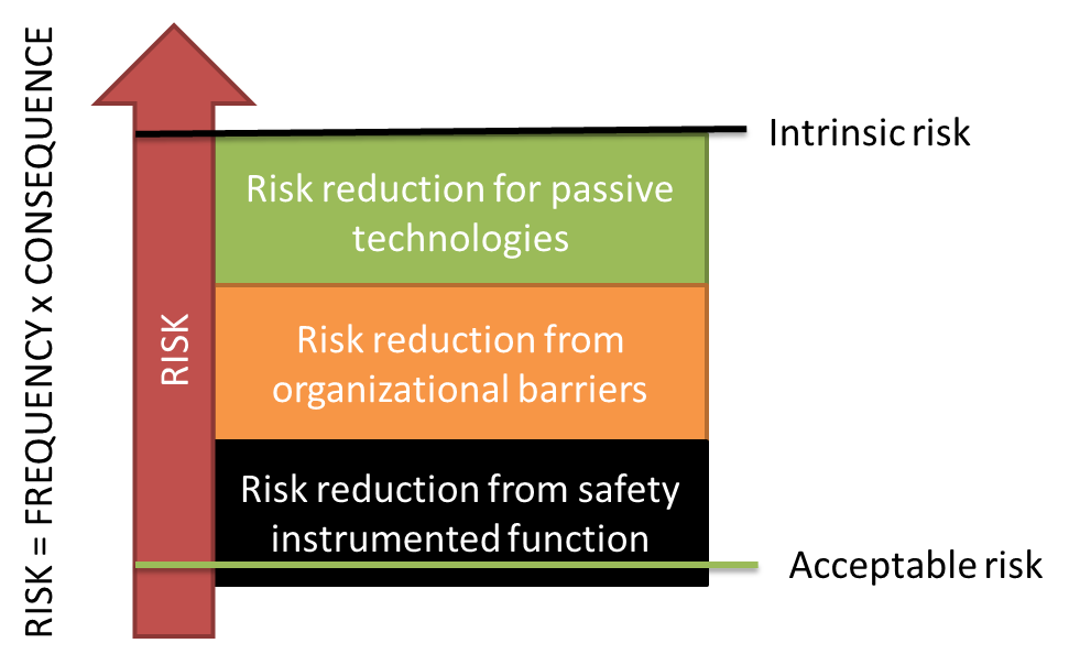
A safety integrity level is a quantification of the necessary risk reduction we need from an automated safety system to achieve acceptable risk levels for some industrial system. The necessary risk reduction, obviously depends also on other activities and systems we put in place to reduce risk from its “intrinsic” level. The following drawing illustrates the role of different things we can do to achieve acceptable risk for a technical asset.

Figure showing how risk reducing measures work together to bring the risk down to an acceptable level.

Consider for example a steel tank that is filled with pressurized gas. One potential hazard here is overpressure in the tank, which may cause a leak and the gas can be both toxic and flammable – obviously a dangerous situation. When working with risk, we need to define what we mean by risk in terms of “acceptance criteria”. In this case, we may say that we accept an explosion due to leak of gas and ignition of the gas afterwords once every one million years – that is a frequency of 10-6 per year. The initial frequency is maybe 0.1 per year, if the source of the high pressure is a controller intended to keep the pressure steady over time by adjusting a valve. Normally, such process control loops have one malfunction every 10 years (a coarse rule of thumb). Passive technologis can here be a spring-loaded safety valve that would open on high pressure and let the gas out to a safe location, for example a flare system where the gas can be burnt off in a controlled manner. This reduces the probability by 99% (such a passive valve tends to fail no more often than 1 out of 100 times). In addition to this, there is an independent alarm on the tank, giving a message to an operator in a control room that the pressure is increasing, and the oprator has time to go and check what is going on, and shut off supply of gas to the tank by closing a manual valve. How reliabile is this operator? With sufficient time, and allowing for some confusion due to stress, we may claim that the operator manages to intervene 9 out of 10 times (such numbers can be found by looking at human reliability analysis – a technique for assessing performance of trained people under various situations – developed primarily within the nuclear industry). In addition, a terrible explosion does not automatically happen if there is a leak – something needs to ignite the gas. Depending on the ignition sources we can assign a probability to this (models exist). For this case, let us assume the probability of ignition of a gas cloud in this location is 10%. We have now reduced the probability of this occuring by a factor of 1000 from an initial “intrinsic” frequency of 0.01. The frequency of such explosions due to leak in the tank before using any automatic shutdown system is thus 0.01 x 0.001 = 0.00001 = 10-5. The remaining reduction needed to bring the frequency down to 1 in a million years for the explosion is then an automated shutdown function that does not fail more than 1 out 10 demands – a PFD of 0.1. This means, we need a safety instrumented function with a probability of failure on demand of 0.1 – which corresponds to a SIL 1 requirement. The process we used to deduce this number is by the way known as a LOPA – a layers of protection analysis. The LOPA is one of many tools in the engineer’s toolbox for performing risk assessments.

What this illustrates is that the requirement to an automated shutdown function depends on other risk mitigation efforts – and the reliability of those barrier elements. What if the operator does not have time to intervene or cannot be trusted? If we take away the effect of the operator’s actions we see immediately that we need a SIL 2 function to achieve acceptable level of safety.

What does a “SIL” requirement really mean?

Safety instrumented systems are often assigned a “Safety Integrity Level”: This is an important concept for ensuring that automatic controls intended to maintain the safety of a technical safety actually bring the risk reduction that is necessary. In the reliability standards IEC 61508 and IEC 61511, there are 4 SILs:

  • SIL 1: a failure on demand in 1 out of 10 demands is acceptable
  • SIL 2: a failure on demand in 1 out of 100 demands is acceptable
  • SIL 3: a failure on demand in 1 out of 1 000 demands is acceptable
  • SIL 4: a failure on demand in 1 out of 10 000 demands is acceptable

This way of defining the probability of failure applies to so-called “low-demand” systems. In practice that means that the safety function does not need to act more than once per year in order to stop an accident from occurring.

The SIL requirement does not only involve probability calculations (Probability for failure on demand = PFD). The SIL consists of four diffent types of requirements:

  • Quantitative requirement (PFD, defined as probability of failure when there is a demand for the function)
  • Semi-quantitative requirements (requirement for redundancy, for a certain number of possible failures of the system leading to a safe state – the socalled safe failure fraction)
  • Software requirements (a lot of the actual control functionality is implemented in software. For this a work process oriented take on things is required by the standards – implications increase in rigor with increasing SIL)
  • Qualitative requirements (avoidance of systematic errors, quality mangement, etc.)

Most people focus only on the quantitative part and do not think about the latter thre parts. In order for us to have trust in the probability assessment, it is necessary that issues that cannot be quanitifed are properly managed. Hence – to claim that you have achived a certain SIL for your safety function, you need to document that the redundancy is right, that most failures will lead to a safet state, that your software has been developed in accordance with required practices and using acceptable technologies, and that your organization and workflows ensure sufficient quality of your safety function product and the system it is a part of.

If people buying components for safety instrumented systems would keep this in mind – it would become much easier to actually create safety critical automation systems with can trust with a given level of integrity.

Planning lifecycle activities for safety instrumented systems

Modern industrial safety instrumented systems are often required to be designed in accordance with IEC 61508 or IEC 61511. These standards about functional safety take a lifecycle view on the safety instrumented system. Most people associate this with SIL – or safety integrity levels, which is an important concept in these standards. Many newcomers to functional safety focus only on quantitative measures of reliability and do not engage with the lifecycle process. This leads to poorer designs than necessary, and compliance with requirements from these standards is not possible without taking the whole lifecycle into account.

A good way to look at a safety instrumented system, is to define phases of the lifecycle, and then assign activities for managing the safety instrumented system throughout these phases. Based on IEC 61511 we can define these phases as:

  • Design
  • Construction
  • Commissioning
  • Operation and maintenance
  • Decomissioning

In other words – we need to manage the safety instrumented system from conception to grave – in line with asset management thinking in general. For each these phases there will typically be various activities related to the safety instrumented system that we will need to focus on. For example, in the design phase we need to focus on identifying the necessary risk reduction, performing risk analysis and determining necessary SILs for the different safety instrumented functions making up the system. A key document emerging from this phase is the “Safety Requirement Specification”. Typically, in the same phase one would start to map out vendors and put out requests for offers on equipment to buy. A guideline for vendors on what type of documentation they should provide would also be good to prepare in this early phase. The Norwegian oil and gas association has made a very nice guideline (Guideline No. 070) for application of functional safety in the oil industry; this guideline contains a very good description of what type of documentation would need to be collected. This is a good starting point.

Also part of design, and typically lasting into the construction phase as well, we would find activities such as compliance assessment (it is necessary to check whether the requirements in the SRS are actually fulfilled, based on documentation form eqipment vendors and system integrators). In addition, at this point it is necessary to complete a Functional Safey Assessment (FSA), a third-party review in the form of an audit to check that the work has been done the way the standards require us to.

Part of the plan should be on how to commission the safety instrumented system. When are the different functions tested, what type of verifications are we doing on the programming of actions based on inputs? Who is responsibel for this? All of this should be planned out from the start.

Further, when the system is taken into operation, the complete asset (including the SIS) is delivered to the company that is going to operate it. The owner is then responsible for maintenance of the system, for proof testing and ensuring that all barrier elements necessary for the system to work are in place. These type of activities should be planned as well.

Finally, the end-of-life for the asset should be managed. How to actually manage that should be part of the plan – taking the system out of service as a whole or only in parts shoudl still be done while maintaining the right level of safety for people, environment and other assets that may be harmed if an accident should occur.

Finally, there are a number of aspects that should be included in a plan for managing functional safety, that span over all these lifecycle phases. These are things like competence management of people involved in working with the SIS in the different lifecycles, how to deal with changes of the system or the environment the system is operating in, who is responsible for what and how to communicate across company interfaces – this list is not exhaustive. Consult the standards for looking at the details.

If all organizations involved in functional safety design would plan out their acitivites in a good way fewer changes would occur towards the end of large engineering projects, better quality would be obtained at a lower cost. And this, is a low-hanging fruit that we all should grab.